Programmable Logic Controller (PLC)
Connection Example with a Mitsubishi Electric PLC (MELSEC iQ-R Series Sequencer)
A high-speed counter unit is required for connection between our servo and the PLC. The connection diagram shown uses an RD62 high-speed counter unit (sink output type).
⇒ Click here for details on Operation via RS485 Communication.
Operation via PWM Signals
A high-speed counter unit is required for connection between our servo and the PLC. The connection diagram shown uses an RD62 high-speed counter unit (sink output type).
Connection Example
Required Equipment
| Pull-up resisto (approx. 47 kΩ) | Required because the PWM signal output point (A06) uses an open-collector output |
| Power supply ×2 | Used for signal voltage and operating power supply voltage |
| PC | Used to write data to the PLC CPU unit |
| USB cable | Connection between the PLC and PC |
PLC Units
| R35B | Main base unit |
| R61B | Power supply unit |
| R00CPU | CPU unit |
| RD62D2 | High-speed counter unit |
| RX40C7 | Input unit |
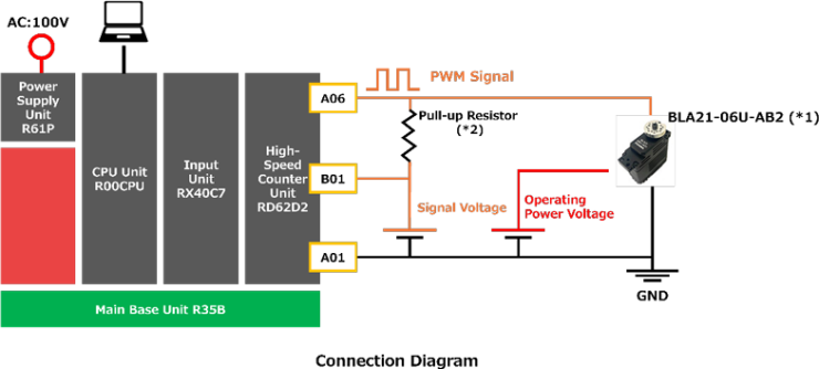
- The connection diagram has been verified for operation only with the BLA21-06U-AB2. Operation is not guaranteed for all of our servo models.
Please prepare the power supplies for the servo signal voltage and operating power voltage based on the following specifications listed in the product specification sheet:- Signal voltage: Signal Voltage (HIGH: max)
- Operating power voltage: Operating Voltage
- Output current: Starting Current (Design value)
- Reference values used in the connection example are shown below:
- Pull-up resistance: 47 kΩ
- Signal voltage: Approx. 3.3 V (measured in-house)
Operation via RS485 Communication
A serial communication unit is required for RS485 communication between our servo and a PLC. The connection diagram shown uses the RJ71C24-R4 serial communication unit.
Connection Example
Required Equipment
| Power supply | Used for the servo operating voltage |
| PC | Used to write data to the PLC CPU unit |
| USB cable | Connection between the PLC and PC |
| Servo accessory cable | Cable for connecting the servo, PLC, and power supply (Modify one connector end as required for connection to the PLC and power supply.) |
PLC Units
| R35B | Main base unit |
| R61B | Power supply unit |
| R00CPU | CPU unit |
| RJ71C24-R4 | Serial communication unit |
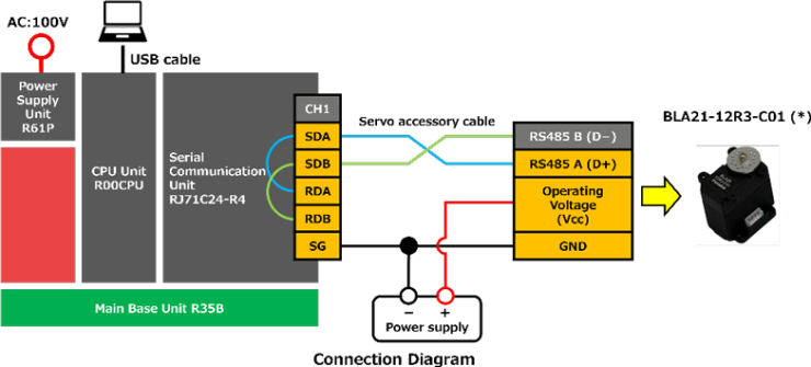
- The connection diagram has been verified for operation only with the BLA21-12R3-C01. Operation is not guaranteed for all of our servo models.
Please prepare the power supply for the servo according to the following specifications listed in the product specification sheet:- Operating voltage: Operating Voltage
- Output current: Starting Current (Design value)
If communication errors occur due to signal reflection or radiated noise, install termination resistors.
Termination resistors should be installed at the following two locations:- Between the RS485 A (D+) and B (D−) terminals on the unused connector of the servo cable
- Between the RDA and RDB terminals on the RJ71C24-R4 terminal block
Please note: We are unable to provide support for Mitsubishi Electric PLCs (MELSEC iQ-R Series). For inquiries regarding PLC operation or programming, please contact Mitsubishi Electric directly.